Motherboard Wiring
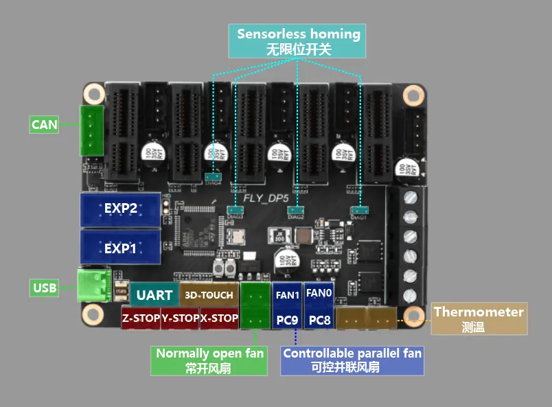
Interface Diagram
Interface Description
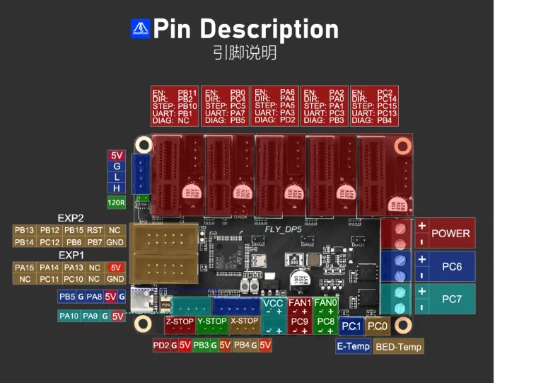
Pin Description
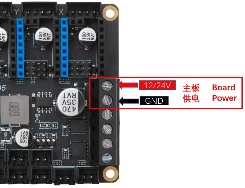
Power Wiring
Driver Installation
Motherboard Driver Jumper
- DP5 does not require installing a driver jumper cap.
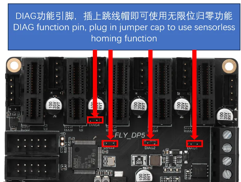
Sensorless Pins
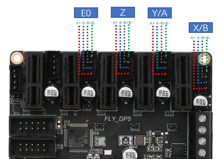
Stepper Motor Wiring
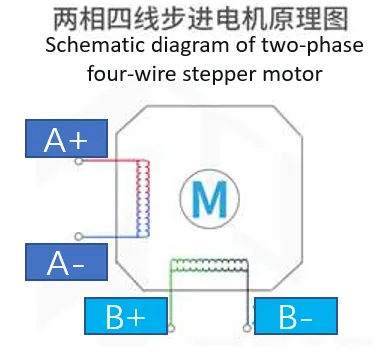
- Regardless of the manufacturer, a two-phase stepper motor ultimately presents as 4 wires. Regardless of color (e.g., black, white, green, yellow), they correspond to 4 wires. Therefore, we need to group the wires into two groups: A and B.
- For a two-phase, four-wire stepper motor, we don't need to know which group is A and which is B; the main thing is to determine that they are a group. The motor direction can be modified in the configuration.
-
In 3D printers, the most commonly used stepper motor is the two-phase, four-wire type. Its principle is shown in the diagram below. There are two methods to identify the stepper motor wire sequence:
- Connect any two phase wires and manually rotate the motor shaft. If significant resistance is felt, then the two phase wires belong to the same group. Otherwise, they are not in the same group, and other phase wires need to be tested.
- Use a multimeter set to the continuity test mode. Test any two phase wires of the stepper motor. If they are connected (beep), they belong to the same group. Otherwise, they are not in the same group, and other phase wires need to be tested.
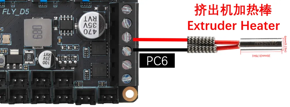
Heater Cartridge Wiring
Heated Bed Wiring
-
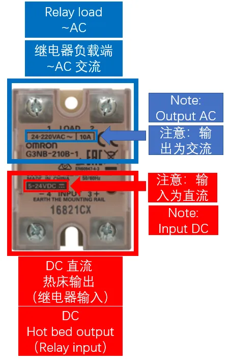
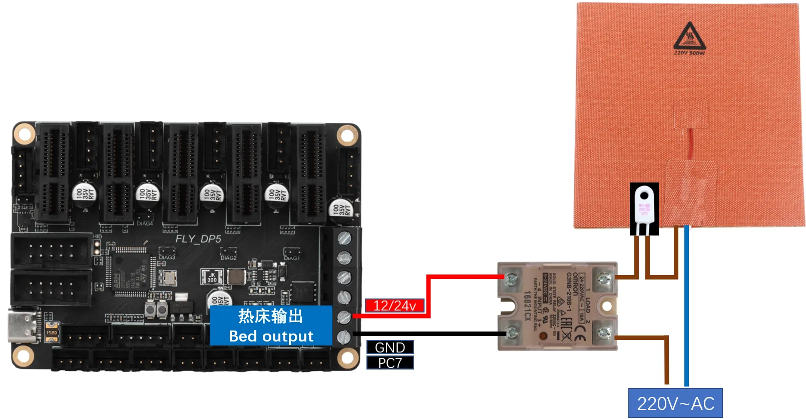
AC Heated Bed: When wiring the solid-state relay, please be careful not to mix up the input and output connections.
-
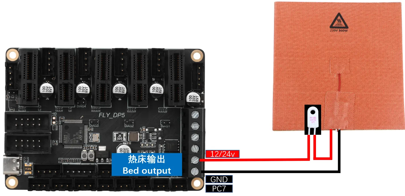
DC Heated Bed: When connecting a DC heated bed to the onboard MOSFET, please pay attention to the power usage. The maximum current for a DC heated bed should not exceed 10A. If it exceeds 10A, it is recommended to use an external MOSFET module for the heated bed. Otherwise, it may cause irreversible damage to the motherboard.
Thermistor Wiring for Temperature Measurement
Thermistor Type Introduction
-
The wiring method for thermistors is shown in the diagram below. Please consult the seller for the type of thermistor.
-
If purchased from FLY (as shown in the image below), please set
sensor_typeto: ATC Semitec 104GT-2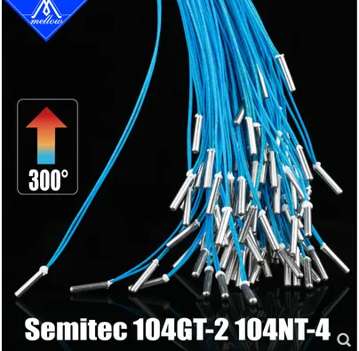
-
If it is a standard NTC 100K (as shown in the image below), please set
sensor_typeto: Generic 3950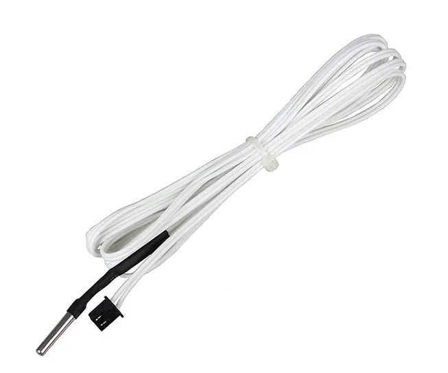

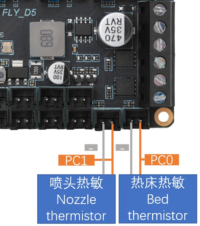
Motherboard Thermistor Wiring
Fan Wiring
-
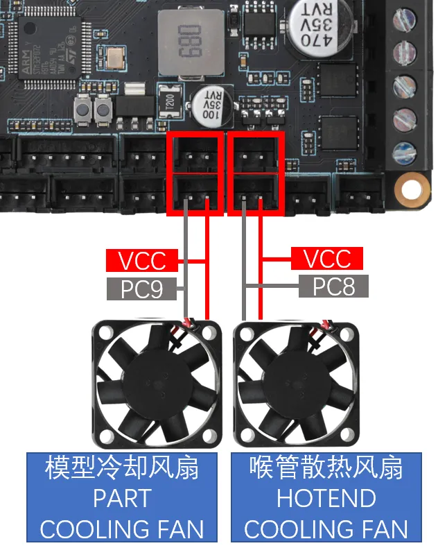
Fan Wiring
tipThe interfaces outlined in the red box in the diagram below are controlled by the same pin, meaning it's a one-to-two controllable fan setup.
Endstop Switch Wiring
-
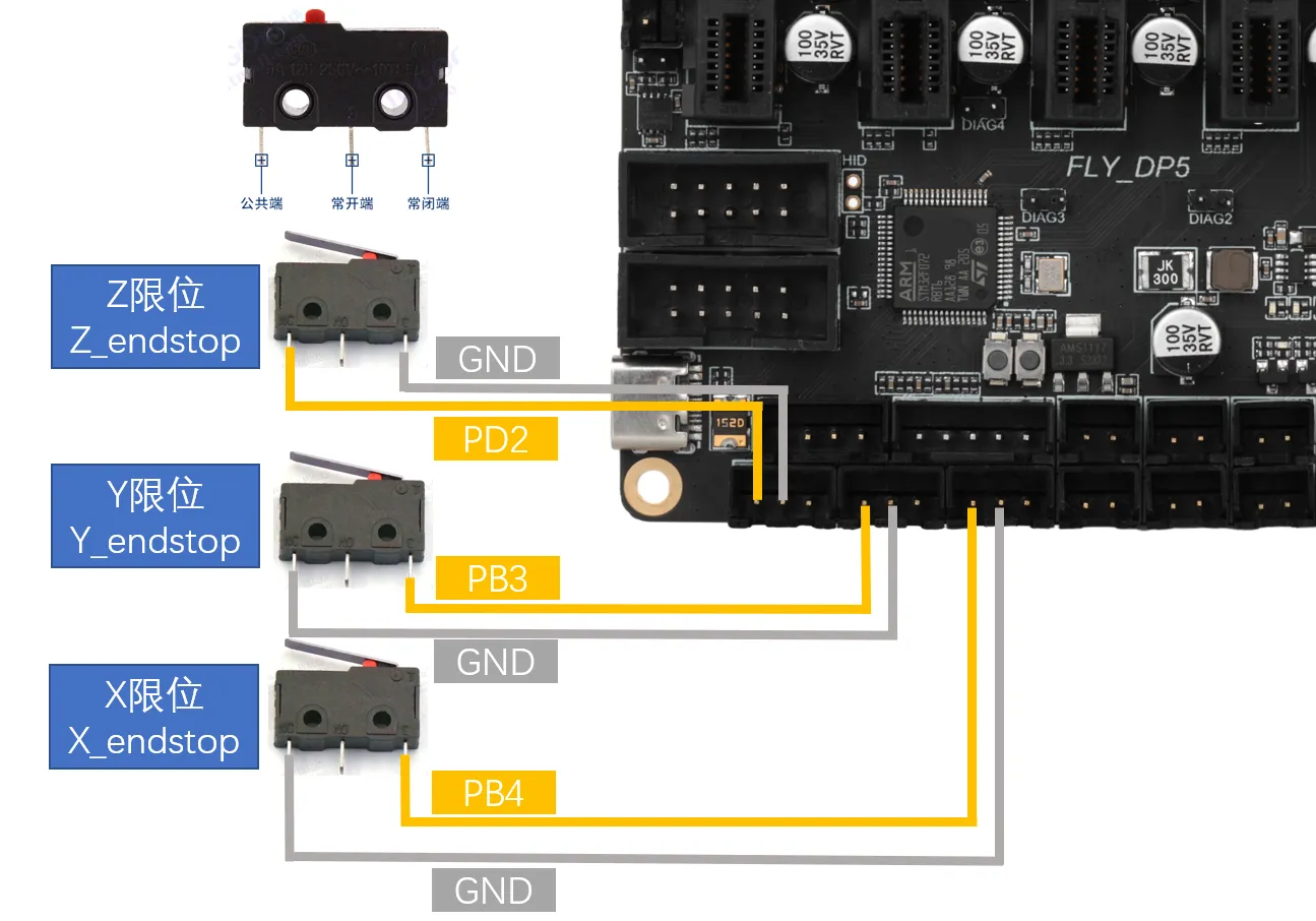
Endstop switches come in Normally Open (NO) and Normally Closed (NC) types. For 3D printers, it is generally recommended to use Normally Closed (NC). This way, if there is a problem with the endstop switch wiring, the system will promptly report an error, which can help avoid unnecessary collisions and prevent damage to the printer.
Bed Leveling Sensor Wiring
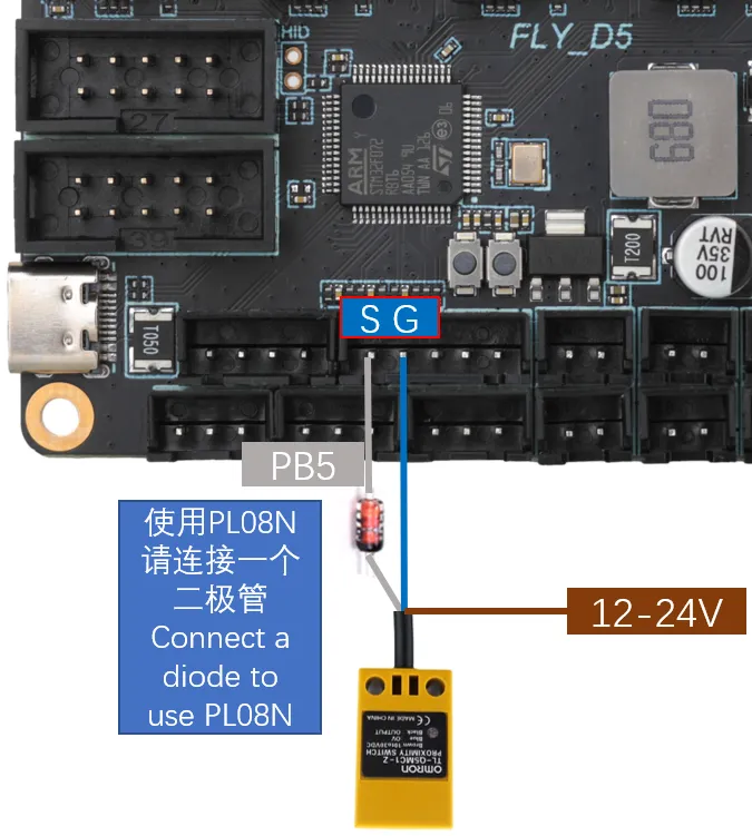
Metal Proximity Switch Wiring
-
VORON officially recommends using the Omron TL-Q5MC sensor (previously the PL08N was recommended; both work on the same principle, only the detection distance differs) for heated bed leveling. The wiring method is shown in the diagram below.
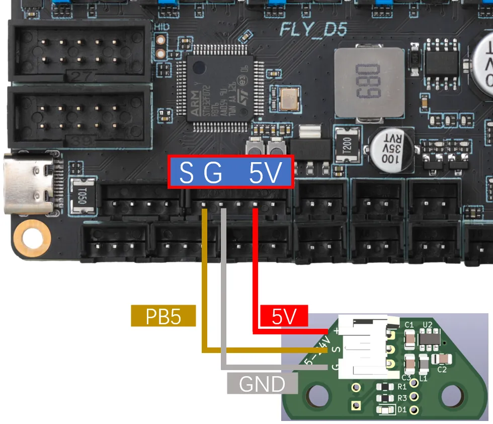
BL-Touch Wiring
-
The BL-Touch has five wires in total. Three wires form the first group, responsible for powering the sensor and controlling the probe extension/retraction. The second group consists of the ground wire and the signal wire, which outputs the limit signal. Please carefully check the wire sequence when wiring the BL-Touch. Incorrect wiring may permanently damage the sensor and the motherboard!!! The wiring method is shown in the diagram below.
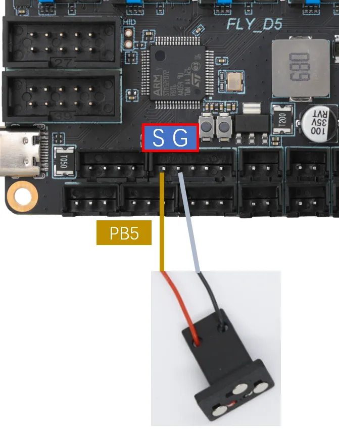
Klicky Wiring
-
Klicky is a third-party bed leveling sensor. It can be made at home at a very low cost, offers stable performance, and is highly cost-effective. Its use is recommended. The wiring method is shown in the diagram below.
-
Project Address: jlas1/Klicky-Probe
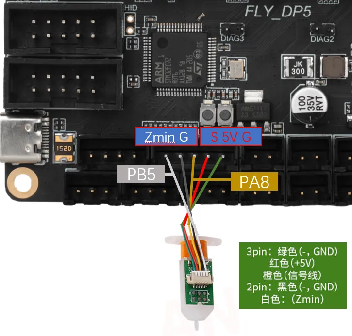
Voron Tap Wiring
-
Tap is a nozzle-based Z-probe designed for V2 and Trident printer designs. The entire toolhead moves to trigger an optical switch, offering better accuracy than conventional endstop switches and compatibility with almost all printing platforms on the market.
warningIt is not recommended to connect Voron Tap to 24V. Certain versions have a probability of burning out the Tap sensor when using 24V. This is not an issue with FLY products but rather a design flaw in Voron Tap. Please be aware!!!
dangerousNote: Do not reverse the 5V and GND connections, as this may damage the Tap sensor or even the motherboard!!!
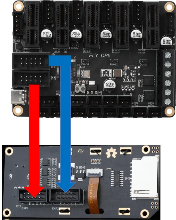
FLY-Mini12864 LCD Wiring
-
The diagram below shows the wiring method for FLY's mini12864. For screens from other manufacturers, please consult the respective manufacturer. Incorrectly wiring or reversing the connections on a Mini12864 screen may cause the host computer to fail to connect to the MCU. If you could previously connect to the motherboard's MCU normally before using the mini12864 but cannot after connecting it, please try unplugging the mini12864 wiring!!!
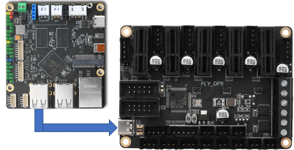
Connecting to the Host Computer
-
The motherboard connects to the host computer's USB port via a Type-C interface. It can also connect via a serial port. Only the former method is introduced here.