Install BDsensor-m
Connect the sensor cable to the EXP1 interface of the motherboard
- If the sensor cable is not long enough, you can use the extension cable included in the package.
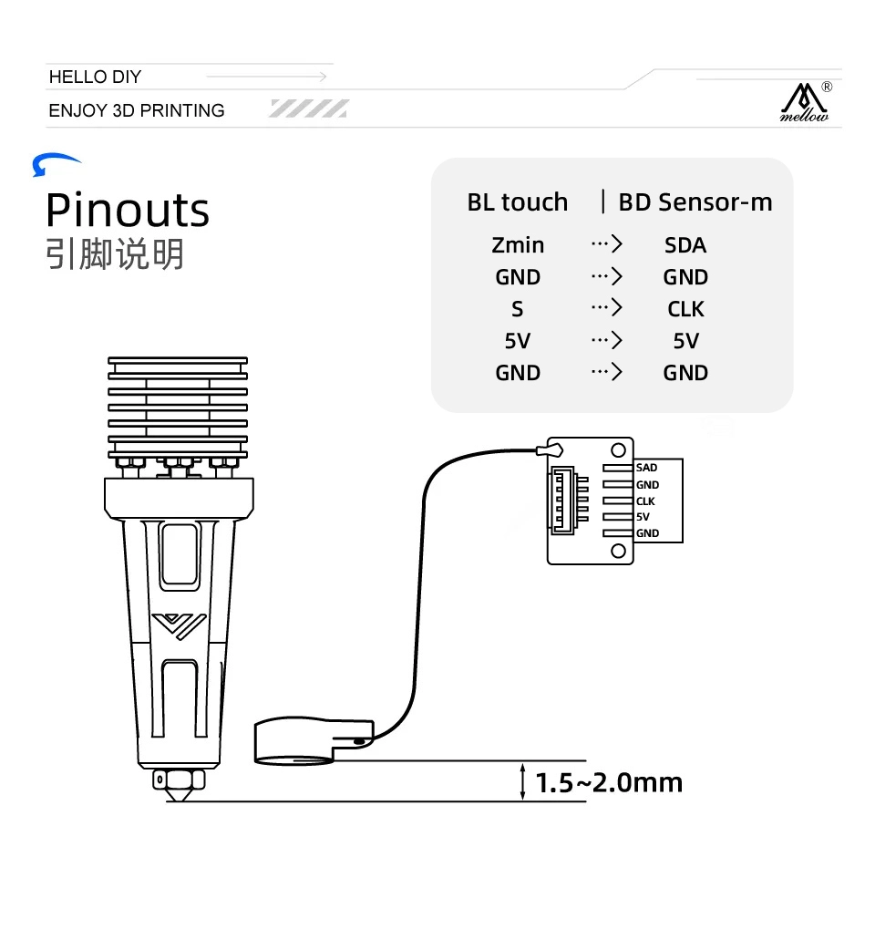
- The CLK and SDA lines of BDsensor-m can be connected to any GPIO pin on the board. You can also directly connect the BD sensor cable to the BLtouch port, for example:
BLtouch    |    BDsensor-m
5V       -->     5V
GND      -->     GND
S        -->     CLK/SCL    (Input)
GND      -->     GND
Zmin     -->     SDA    (Input/Output)
- Some pins in the motherboard connector may not be directly connected to the MCU's gpios (e.g., they may have filtering capacitors or are isolated through MOSFETs, diodes, or optocouplers, although they may still be usable if isolated via resistors or resistor pull-ups/pull-downs), so they cannot be used with
BDsensor-m. The firmware will report a connection error. Examples include: - Fan and heater connectors that are isolated through MOSFETs.
- Connectors on some boards for thermistors and endstops/probes that are typically connected to GND through filtering capacitors.
-
As shown in the image below, install the BD sensor near the hot end. STL of mount, STL_mount_VzBot_Goliath short
Install the patch into the klipper firmware
-
Do not perform steps not mentioned in this tutorial.
-
Discard any previous modifications made to klipper files and update klipper:
cd
cd ~/klipper
git checkout .
git pull -
Execute the following git command in your home directory to clone the latest BD sensor code:
cd && git clone https://github.com/markniu/Bed_Distance_sensor.git -
Then execute the following command to install:
cd  ~/Bed_Distance_sensor/klipper/
./install_BDsensor.sh
Recompile the firmware if there is a prompt about mismatch between host and MCU firmware
-
Refer to the firmware compilation guide for your specific board to compile and flash the firmware.
-
Compile the firmware:
cd ~/klipper/  # Navigate to the klipper directory
make menuconfig  # Command to enter klipper configuration interface
make clean  # Clean build command
make # Build command -
Flash the compiled firmware to the motherboard where BDsensor is connected.
If your printer runs Moonraker, add the following section to moonraker.conf. Then you can update BDsensor with a single click via the web interface or KlipperScreen.
[update_manager BDsensor]
type: git_repo
primary_branch: new
channel: dev
path: ~/Bed_Distance_sensor
origin: https://github.com/markniu/Bed_Distance_sensor.git
install_script: ./klipper/install_BDsensor.sh
is_system_service: False
managed_services: klipper
info_tags:
desc=Bed Distance Sensor
Edit printer.cfg
-
Copy this section to your printer.cfg and edit the
sda_pinandscl_pinunder[BDsensor]. Also, remember to disable other probe sections such as BLtouch. You can connect the BD sensor to either the motherboard or the toolhead CAN module. -
In
[BDsensor], change thespeedto 0.8. This only applies to z tilt and the PROBE_ACCURACY command. A smaller value means higher probing accuracy because the MCU reads the BD sensor in the main loop during homing, not in real-time like a normal endstop. -
To use the BD sensor as an endstop during Z-axis homing, change the
endstop_pinin[stepper_z]toendstop_pin: probe:z_virtual_endstop. -
Ensure that
[safe_z_home]is present in printer.cfg. -
Change the value in
[bed_mesh]and[z_tilt]or[quad_gantry_level]to 1 (recommended 0.7-1.0 mm). The default value in klipper is 5 mm, which could easily exceed the sensor range. -
Nozzle height adjustment should only be done via
z_adjust:. Positive values bring the nozzle closer to the bed, while negative values move it away. Other nozzle height adjustment settings may cause bugs. -
To enable fast bed probing, remove the
#beforeno_stop_probe:true. -
Below is a configuration example:
[BDsensor]
scl_pin:PC6  # Servo signal pin
sda_pin:PC3  # Endstop signal pin
delay: 20 # 20us per pulse, this value should be >=20 but must be below 50
z_offset:0 # this `z_offset` must be set to 0.
z_adjust:0.0 # z axis adjustment, replace the z_offset function. within -0.3 to 0.3mm
x_offset: -34
y_offset: 0
#no_stop_probe:true # enable this for fast probe, the toolhead will not stop at the probe point.
position_endstop: 0.8 # the Z axis will stop at this position (mm) while homing z, recommend value is 0.4~1.0
#speed:0.8 # this speed only works for the z tilt and PROBE_ACCURACY command.

[stepper_z]
endstop_pin: probe:z_virtual_endstop
#position_endstop: 0.5
homing_speed: 5
second_homing_speed: 0.8

[bed_mesh]
speed: 200
horizontal_move_z:1
algorithm: bicubic

[quad_gantry_level]
horizontal_move_z:1
After installation, check it by sending the following G-code commands:
M102   S-1     # Read sensor information
M102   S-2     # Read a distance value
Check the connection
-
Send
M102 S-1via the console; this is an example of a returned message. If nothing or other strings are returned, check the connection and wire order:Send: M102 S-1
Recv: V1.0 pandapi3d.com
Calibration
- Clean the nozzle and manually move the Z-axis via the console until the nozzle just touches the bed (BDsensor-m will use this position as the zero position, so no
z_offsetis needed. This is why the value in the [BDsensor-m] section is 0). - Send the G-code command
M102 S-6via the console; the printer will slowly raise the Z-axis by 0.1 mm until reaching 4 mm. Do not run M102 S-6 before installing the sensor, nor power off the printer during calibration, or the old calibration data will be deleted. In that case, recalibrate. - Afterwards, you can check whether the BD sensor was successfully calibrated via
M102 S-5, which will return the stored raw calibration data from the BD sensor.
Notes:
-
Homing Z-axis speed is best set to 5.
-
If M102 S-5 returns a first raw calibration value greater than 400, it means the sensor is mounted too high and needs to be reinstalled closer to the bed; the recommended first value is around 100. Also ensure that the second value is at least 10 units higher than the first.
-
FAQ: What does it mean if the calibration data starts with 1 as the first value, 9 as the second, and 24 as the third?
-
It means the resolution between 0-0.1 mm is only 9, and between 0.1-0.2 mm is 15. Therefore, it is recommended to recalibrate and ensure the resolution in the 0-0.1 mm range is greater than 10.
-
-
Don't forget to adjust the Z-axis height after running G28 or for commands such as
Z_tiltandquad_gantry_level. -
Section names must be correctly capitalized; otherwise, klipper will report
Unknown pin chip name 'probe'.